What is the manufacturing process of TFT LCD Display?
Display screen is everywhere nowadays. Do you still remember the TVs or computer monitors 20 years ago? They were quadrate, huge and heavy. Now let’s look at the flat, thin and light screen in front of you, have you ever wondered why is there such a big difference?
Actually, the monitors 20 year ago were CRT (Cathode Ray Tube) displays, which requires a large space to run the inner component. And now the screen here in your presence is the LCD (Liquid Crystal Display) screen.
What is LCD?
As mentioned above, LCD is the abbreviation of Liquid Crystal Display. It’s a new display technology making use of the optical-electrical characteristic of liquid crystal.
Liquid crystal is a state of substance that has both the characteristics of liquid and solid crystal. It don’t emit light itself, but it can let the light pass perfectly in specific direction. Meanwhile, liquid crystal molecule will rotate under the influence of a electric field, and then the light goes through it will rotate too. That said, liquid crystal can be a switch of light, which is the key in display technology.
Types of LCD
LCD has been developed for decades. Basically there are TN LCD, STN LCD and TFT LCD.
TN LCD: TN is for Twisted Nematic. It’s a old and simple technology that can only display white and black, used in small stuffs like calculator.
STN LCD: STN is for Super-twisted Nematic. The liquid crystal in STN LCD rotate more angles than that in TN LCD, and have a different electrical feature, allowing STN LCD to display more information. There are many improved version of STN LCD like DSTN LCD (double layer) and CSTN LCD (color). This LCD is used in many early phones, computers and outdoor devices.
TFT LCD: TFT is for Thin Film Transistor. It’s the latest generation of LCD technology and has been applied in all the displaying scenario including electronic devices, motor cars, industrial machines, etc. When you see the word ‘transistor’, you may realize there’s integrated circuits in TFT LCD. That’s correct and the secret that TFT LCD has the advantage of high resolution and full color display.
Now that TFT LCD has the largest application market, let’s go one step further and see what’s the manufacturing process of TFT LCD.

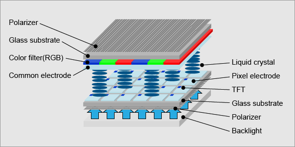
TFT LCD structure
Manufacturing process of TFT LCD
In a simple way, we can divide TFT LCD into three parts, from bottom to top they are: light system, circuit system and light and color control system.In manufacturing process, we’ll start from inner light and color control system and then stretch out to whole module.
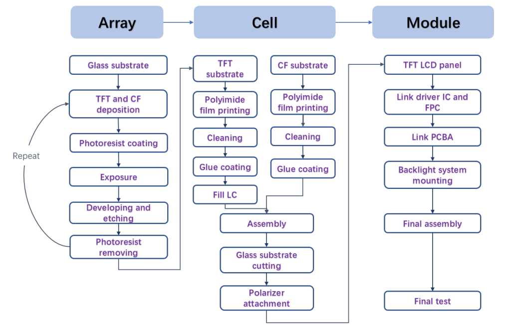
It’s accustomed to divide TFT LCD manufacturing process into three main part: array, cell and module. The former two steps are about the production of light and color control system, which contains TFT, CF (color filter) and LC (liquid crystal), named a cell. And the last step is the assembly of cell, circuit and light system.

TFT LCD Manufacturing flow chart
1. Array
In order to enhance productivity, in this step we’ll do a series of procedure on a large glass, which will be cut into smaller pieces in the following step.
First, let me introduce a crucial material, ITO, to you. ITO, abbreviation of Indium tin oxide, has the characteristic of electrical conductivity and optical transparency, as well as can be easily deposited as a thin film. Thus it’s widely used to create circuit on glass.
Now let’s turn to the production of TFT and CF. Here is a common method called PR (photoresist) method. The whole process of PR method will be demonstrated in TFT production.
TFT:
- ◇ Deposit semiconductor material and ITO in designed order on glass substrate.
- ◇ Photoresist coating.
- ◇ Partial exposure, then clean the exposed photoresist.
- ◇ Tear off the semiconductor and ITO without the cover of photoresist to form part of the circuit.
- ◇ Clean the remain photoresist.
- ◇ To build the whole circuit, we often need to repeat the steps for 5 times.
CF:
- ◇ Create a black matrix on the glass substrate as the boundary using PR method.
- ◇ Coat red, green and blue material within black matrix separately using PR method.
- ◇ Coat a overcover on RGB (red, green and blue) layer.
- ◇ Deposit ITO circuit.
2. Cell
In this step we’re going to assemble the TFT and CF glass and fill in LC at the same time.
- ◇ Coat polyimide film, using to constrain the initial direction of LC molecule, on the ITO side of both TFT and CF glass.
- ◇ Use glue to build a boundary for LC on both glass. And on CF glass, apply one more layer of conductive adhesive. This enable LC molecule link to the control circuit.
- ◇ Fill LC within the boundary.
- ◇ Stick two glass together, then cut the large glass into small pieces in line with standard.
- ◇ Attach polarizer film on the both side of the incised glass.
3. Module
First link the cell to circuit system.
- ◇ Link the cell to driver IC.
- ◇ Link driver IC to FPC (flexible printed circuit).
- ◇ Link FPC to outer PCBA (printed circuit board assembly).
Next prepare the light system
- ◇ Attach the light source, usually LED or CCFL, on light guide plate, under which there is reflector film
- ◇ Put the diffuser film and prism film on light source in turn. Together with reflector film, these two films are used to turn the point light from light source into area light and enhance light intensity.
- ◇ Link the light source to light control circuit, always another type of PCBA.
In the final step, we need to assemble all these together with the screen frame, and do a aging test.

The information below is required for social login
Sign In
Create New Account